|
Discussion:
This procedure will detail the steps necessary to replace the Rod Bearings on a 944 Turbo car. With some modifications it may also be applied to normally aspirated 944 cars too, and potentially the 968 model line.
The Rod Bearings seem to be a weak link in the 944 series engines (including the 924S here same engine as a 944 NA). During hard cornering the oil in the pan can slosh away from the oil pickup starving the engine for oil. In a worse case scenario, the rod bearings can spin causing severe engine damage (usually #2 is the culprit though I know of at least one car that had #3 go, and my #4 bearing was in BAD shape. Read that as new crank, new connecting rods, new oil pump and new pistons also necessitating removal of your engine.)
It makes sense at least to me to consider replacing the rod bearings as preventative maintenance. Its a long job, but its also a job thats not too difficult with the right tools, and the right instructions.
Ive done a bit of research on the approximate mileage that bearings seem to last prior to spinning but cant find a direct correlation between mileages, age of the car, track usage and the dreaded bearing spin. The only common item I can see is that in all cases that Im aware of, the car had more than 100,000 miles on it. A couple heavily tracked cars had over 150,000 miles on them. Bottom line if you track the car at all, or have close to 100,000 miles do this now.
There is some debate going on as to the use of plastigage on the new bearings
Once school of thought is that if you use it youll be sure of the clearance. The other is that as soon as you torque down the bearings the first time, they become warped a little, and removal necessitates replacement of the bearing, thus invalidating any use of the plastigauge. My opinion is that if theres a problem you want to find out NOW. Not after the car is all back together so I use it. Religiously.
Lastly before starting the actual procedure, a suggestion. Check your oil and run it a little higher than the norm especially if youre tracking the car. An couple extra ounces of oil (I use ½ a quart) can save you a 12 hour procedure or worse.
Hopefully this procedure helps youre looking at a savings of over $1400.00 (usual quote) by performing this procedure yourself.
Tools Needed:
-
Safety goggles which you should put on before step one!
-
Set of Metric sockets (both deep and shallow)
-
Set of Socket Extensions (short and long)
-
Socket Wrench
-
Set of Metric wrenches (10mm-19mm)
-
32mm Socket (for oil drain on Turbo into Oil Pan a large wrench might work well too)
-
6mm Allen head socket or wrench
-
Torque Wrench capable of 3 ft pounds to 96 foot-pounds
-
Screwdrivers normal
-
Pickle fork for removing tie rod ends
-
Several clean rags
-
Drain pan for oil
-
Drain pan for coolant
-
Drain pan for power steering fluid
-
Penetrating oil
-
Cleaner of some sort (Brake cleaner works well here)
-
Plastigage
-
Engine Hoist or brace for the engine
-
Floor jack with a piece of wood to protect the bottom of the car.
-
Jack stands (at least 2, Id suggest 4 to be safe)
-
Cord to tie things
-
At least a 12 pack of your favorite beverage. Any German beer would suffice.
-
Lots of patience.
Parts Needed:
-
Oil Pan Gasket (944.101.205.02)
-
Red RTV, or Locktite (Silastic 730)
-
Dental Floss (Trust me
. Minty non-waxed makes your engine smell nice and its usually a nice greenish color.)
-
4 Intake Manifold Gaskets (944.110.163.05)
-
Gaskets for Exhaust (944.111.205.04 3 needed - headers and turbo hotside, 930.123.134.02 waste gate pipe)
-
Rod Bearings (std)
-
8 NEW rod cap nuts (928.103.172.02)
-
Cotter pins (2 small ones for the tie rod ends)
-
Engine assembly lube
-
Clean Engine Oil (Red Line , Red Line Racing , Swepco )
-
Oil filter (Mahle OC-142 , K&N HP-4001)
-
Coolant (Genuine Porsche , Water Wetter )
Things that will be off anyway so now its a good time to replace them:
-
Control Arms (924S/944 early, 944/968 1985.5-1995,
-
Fuel Injectors (944 Turbo , 944S/944S2/944 2.7L, 924S/944 85.5-88)
-
Motor Mounts
-
Belts (AC 924S/944/968 1985.5-1995, 944 83-85.5) and Power Steering)
-
Spark Plugs
-
Distributor Cap (944 8 Valve 1983-1989, 944/968 16 Valve 1987-1995)
-
Rotor (944 8 Valve 1983-1989, 944/968 16 Valve 1987-1995 )
-
Air Filter (944 8 Valve/Non-Turbo 1983-1989 , 944 Turbo, 944S , 944S2, 968 )
-
Ignition wires (944 8 Valve all 1983-1989 , 944 16 Valve, 968)
-
Tie Rod Ends (944 1983-1986 all manual steering, 944 1983-1986 all power steering, 944/968 all)
-
Power Steering Rack will be closer than ever to be off so if it leaks do it now.
Suggested Replacements:
Oil Pan Baffle (updated 944.107.389.01)
This updated part helps prevent oil starvation by adding size to the baffles molded into it. While its not the 100% fix it does help. Any car after 87 should already have it, my 86 didnt. Then again, my baffle came out in 4 pieces anyway
Moral of this story buy the part. If you dont need it you can return it. But it would stink if you needed it late at night to finish up wouldnt it?
Time Estimate: 12 hours for a Turbo
6 hours for a NA car
Level of Difficulty: Novice Mechanic
Procedure:
** Prior to starting the procedure - please put on the safety goggles, and JOIN RENNLIST (http://www.rennlist.com) if you're not a "real live" member!!!! **
-
Depressurize fuel system. (Open the end cap on the fuel rail use rags to catch any fuel that will leak out.)
-
Disconnect the negative terminal of the battery.
-
Remove the coil wire lead to the distributor, and remove the spark plug wires to the plugs.
-
Remove the fuel rail (10mm bolts, 4, holding it to the cam cover. You might have to use a little force to remove it from the intake manifold, pull straight up once the 4 bolts have been removed. )
-
Remove the Throttle cable and cruise control cable (if so equipped).
-
Remove the factory air-box.
-
Remove the 12mm banjo bolt at the rear of the intake manifold, being careful not to loose the 3 washers on it.
-
Remove the two hoses between intake manifold runners 1 and 2, and 2 and 3.
-
Remove the two intercooler hard pipes, leaving the large rubber hose coming off the turbocharger intact on the turbochargers compressor housing. (You can remove the throttle side hard pipe as a unit with the throttle rubber hose attached.
-
Remove the intake manifold. As SOON as you remove it check the tops of the intake valves for pools of gas. If you see a pool of gas, you found a leaking injector. Stuff clean rags into the holes on top of the intake valves to prevent entry of foreign material into the cylinders.
-
Remove the spark plugs, which will make it easier to press up on the connecting rods once you finally see them.
-
Remove the Turbos supplemental water pump. Its held on up top with a 10 mm bolt
Disconnecting the hoses may cause coolant to flood your floor be prepared to catch it.
-
Remove the heat shield around the brake master cylinder. A couple well-hidden 10mm bolts hold it on. BE CAREFUL many people have had to pause the procedure here to go get stitches from cuts this piece of metal inflicts.
-
Spray the crossover pipe bolts at the turbochargers hot side, headers, and the waste gate tube with a liberal amount of penetrating oil.
-
Loosen the lug nuts on the two front tires
-
Jack and brace the car up. Youll need about 20ish inches of clearance for this procedure, but the more space you have to work the happier youll be.
-
Remove the front tires (lug nuts are tightened lubricated with anti-seize to 96 foot pounds)
-
Remove the bottom belly pans
-
Remove the control arms. Scribe marks in them to insure proper placement. Youll need a 19mm wrench and socket combo here. (Some people only remove the 2 connections to the cross member and swing the arm out of the way at the ball joint.)
-
Brace the now floppy strut/rotor combo with cord.
-
Disconnect the Oxygen sensor at the connecter in the engine compartment.
-
Remove the crossover pipe. Disconnect the 6 header bolts; the three holding the crossover pipe to the waste-gate pipe, and the 4 bolts holding it to the turbo. You may have to wiggle it around a bit to get it to come out. If necessary, you may also unbolt the hangers on the catalytic converter to gain some wiggle space.
-
Attach the engine hoist to the engine and take up slack on it so that it is supporting the weight of the engine.
-
Remove the 4 13mm bolts holding the motor mounts to the cross member.
-
Remove the Bottom nuts (17mm) on the motor mounts (the part that you can now see where the control arms mounted to the cross member.
-
Ensure that the engine hoist is doing its job.
-
Remove the lock bolts and cotter pins from the tie rod ends.
-
Disconnect the tie rod ends from the knuckles at the wheels. (Keep whacking it itll come off eventually.)
-
Disconnect the AC adjuster rod (that thing you loosened to get the AC belt off) at one end, and swing it out of the way. Make sure that you loosen the two mounting bolts before loosening the adjuster itself.
-
Remove the power steering belt, and the AC compressor belt. (Trust me on this one
)
-
Move the AC compressor as far away from the oil pan as you can without disconnecting the AC lines.
-
Remove the power steering hose at the power steering pump, making sure not to loose the sealing rings on the banjo bolt. Yup catch that fluid too
Also - at this time mark for alignment with paint, and disconnect the lower steering u-joint by removing the 13mm bolt from the union and prying the union apart. Find it by following the steering rod from the steering wheel down to where it contacts the steering rack.
-
Brace the cross member with the floor jack and a piece of wood, and remove the 4 bolts holding the cross member to the car. Lower it gently (As its STILL CONNECTED by one power steering line) and prop it up so that theres no pressure on that remaining line. I moved mine about 6 inches forward, and gently laid it on a large 4x4.
-
Congrats, you now can see the oil pan unobstructed!
-
Drain the oil if you havent done so yet. A pan coming down with close to 7 quarts of oil in it will make a puddle that will make the rest of the procedure a bit uncomfortable.
-
Remove that LARGE 35mm banjo bolt into the side of the oil pan. Dont loose the sealing rings there too.
-
Brace the oil pan with the floor jack and a piece of wood.
-
Using whatever variety of wrenches, sockets, extensions, or whatever, remove all 22 bolts from the oil pan. Make SURE you get a good bite on the heads this is NOT the place to strip a bolt. Youll have to also remove at least one heat shield to access some of the oil pan bolts. The heat shield that was easy was the one on the passenger side of the car. The other one bolted to the turbos down pipe was a bit more difficult to remove.
-
Lower the oil pan from the car, rotating it gently to insure you clear the oil pickup. CAREFUL here
Once its starting to come down, you might be able to fit your hand in there to help feel the pickup. Itll be coated with oil, and the top of the pickup will have a puddle of oil in it too.
-
You should now see the crank, and the rod end caps. Congrats again!
-
Position the crank at Bottom Dead Center (BDC) for piston one and remove the two rod cap bolts on piston/rod number one.
-
Gently but firmly, pull the end cap off the crank. It comes straight off.
-
Notice the bottom half of the bearing is either on the end cap or still on the crank.
-
Notice the keyways and the direction that they are in on the bearings youre pulling off.
-
Using finger pressure only, push up on the two rod bolts to push the piston up in the cylinder. Take care not to damage the crank in ANY way.
-
Remove the old bearings, and label them for a framed display next to the car.
-
Install the new bearings with a very light coat of oil, and lay a strip of plastigage in the journal.
-
Install two new rod cap nuts on the rod bolts, and torque to 55 foot pounds, then to 59 foot pounds.
-
Position the crank at Bottom Dead Center (BDC) for piston one and remove the two rod cap bolts on piston/rod number one.
-
Gently but firmly, pull the end cap off the crank. It comes straight off.
-
Notice the bottom half of the bearing is either on the end cap or still on the crank.
-
Notice the keyways and the direction that they are in on the bearings youre pulling off.
-
Using finger pressure only, push up on the two rod bolts to push the piston up in the cylinder. Take care not to damage the crank in ANY way.
-
Read the plastigage using the supplied gauge, and insure that the new bearings are within tolerance.
-
Remove the bearings, and clean the crank of all traces of plastigage a credit card works well for this.
-
Coat the new bearings with engine oil, and then place a large drop of assembly lube (penny sized) in the center of the inside of the bearing. Smooth the assembly lube with a CLEAN finger, insuring that nothing but oil and assembly lube are on the bearing.
-
Notice the keyways again, and install the new bearings (top one first, then install the bottom one in the end cap. Insure that the bearings are seated all the way (use your fingers here NO tools as you could scratch the new bearings
) and position the end cap back on the crank.
-
Install two new rod cap nuts on the rod bolts, and torque to 55 foot pounds, then to 59 foot pounds.
-
Rotate the engine twice, to insure there is no binding or additional resistance met. If there is either of the above remove the bearing and start again.
-
Repeat steps 40 through 59 for the remainder of the bearings, substituting piston 2, 3 and 4 for piston one.
-
Once youre all done rotate the engine a couple more times to feel better before you bolt everything together again.
-
Install the updated oil pan baffle in the oil pan. 6 small Allen head screws hold it on.
-
Tie the oil pan gasket to the now perfectly clean oil pan (right?) with the dental floss, at all 4 corners, and at 2 or 3 places around the long sides of the pan.
-
Install the oil pan the longer bolts go in the corners (there are 4 longer bolts) and install the bolts hand tight. Use RTV red (or locktite) on the CORNERS of the pan gasket only.
-
Cut the dental floss as you install the bolts.
-
Torque the oil pan bolts in a clockwise fashion starting from the center of the pan, going across the pan to the other side and around. Use this diagram as a guide. Expand the numbers all the way out to 22 bolts, and once installed hand tight, torque first to 3 foot pounds, and then 7 foot pounds.
10 6 2 3 7 11
Oil Pan
9 5 1 4 8 12
-
The remaining steps are the reverse of removal. Put it all back together now
;)
Wrap-up Notes:
-
Before starting remember to refill the coolant (and bleed the system!), the oil, and the power steering fluid with Dextron!
-
Once all done start the car and let it run for 20-30 minutes at idle.
-
I like taking it easy on the new bearings for about 500 miles but that is personal preference.
Notes from Michael Belfoure:
-
Disconnect the tie rods from the steering knuckle before removing the control arm.
-
Disconnect both power steering hoses and remove the entire crossmember and rack. One is the banjo bolt on the pump and the other is clamped to the hard line in the same area.
-
Do not remove the A/C compressor. I removed the A/C and PS belts and the A/C adjuster. Then I pivoted the compressor as far away from oil pan as possible. To get to those two oil pan bolts, I used a 10mm swivel socket. Not a swivel and socket but the kind that has the socket and swivel in one piece. Saves the headache of holding the compressor out of the way with mechanics wire.
-
[Instead of] dental floss to hold gasket to the oil pan. Since I cleaned the entire oil pan inside and out, I stuck the bolts through the oil pan and gasket just far enough so the tip of the bolt was sticking up about 1/8". Then I put duck tape the bottom of the bolt to the pan. [After] struggled with the dental floss... I sat there looking at it for another 10 minutes until I came up with the duck tape idea (if you can't fix it, duck it!). I found the pan to be very difficult to get lined up. It is almost impossible to know if the rear of the gasket is in the grove at the back of the engine because of the flywheel. When I had all of the bolts in the pan, I took a piece of mechanics wire and "felt" the gasket back there. If the wire went in too far, the gasket wasn't in the groove. I guess I got lucky.
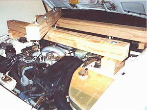
Engine support:
Credits: Jay Cohen (Photos and Notes by Michael Belfoure)
| Related Articles |
> Window Express Kit Installation
> AC Delete
> Accusump Installation
> Adjustable Ride Height Kit - Paragon
> Alternator Replacement
> Brakes, front - 924S, 944, 944S
> Brey-Krause Strut Brace Installation - 944
> Camber Plate Installation (Paragon)
> Clock/Bulb Replacement, digital, Late 944 and 968
> Clutch Replacement - Part One
> Clutch Replacement - Part Two
> Clutch Slave Bleeder Valve Remote
> Control Arm Bushing Upgrade - Weltmeister
> Control Arm, Front - Info
> Coolant Flush
> DME Chip Installation
> Dash Replacement
> Engine Identification
> Engine Production
> Fuel Level Sender
> KLA Strut Brace Installation - 924S, 944, 968
> Koni Strut Conversion - 8641-1414S for late 944, 968
> Motor Mount Replacement
> Odometer Gear Replacement - late 944
> Oil Cooling, Auxiliary
> Oil Pressure Relief Valve
> Oil Pressure Sending Unit Replacement
> Rear Ride Height Adjustment
> Porsche Chronology
> Rear Spring Rates vs. Effective Rates
> Rear Wheel Bearing Diagnosis
> Rear Wheel Bearing Replacement - 924, early 944
> Rear Wheel Bearing Replacement - late 944, 968
> Ride Height Measurement
> Shift Lever Rebuild
> Short Shift Kit
> Throttle Position Sensor
> Sway Bars - Info
> Torque Tube Rebuild
> Torsion Bar Replacement
> Transaxle Fluid - Info
> Transaxle Fluid Change
> Rear Sway Bar Installation
> Transaxle Replacement
> Heater Clip
> Window Regulator Replacement
> Seat Back Brace Installation Instructions
> KLA Strut Brace Installation - 968/944 S2/944 S
|
|
