Window Express Kit Installation Instructions.
Author: Skip
Introduction
Most modern cars have an auto function on the drivers side power window (this kit will also work on the passenger side window).
This is very convenient when entering parking garages and toll booths, grabbing a quick bite at the drive thru, or when closing the window exiting the car. I certainly missed this feature in my 944.
This kit will work in your 911, 924, 944, 928, 968 and VW type vehicles, as the wiring is the same.
This kit will work in any positive switched vehicle (both motor wires at +12v when motor is at rest).
How the unit works
Automatic operation
Press switch in the up direction and release. The window will travel up until it is fully closed.
Press switch in down direction and release. The window will travel down until it is fully open.
Partial operation
When window is traveling up press the switch down momentarily. The window will stop where it is
When window is traveling down press the switch in the up direction momentarily. The window will stop where it is.
Safety
If the window is obstructed during its travel it will stop when stalled as if it had reached the end of its travel, this is a safety feature that operates if you get an arm or hand caught etc.
Construction
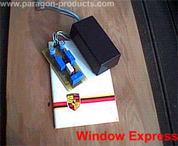
The circuit is built on a professionally etched fiberglass circuit board and is sealed in a plastic box.
Installation (944)(positive switched vehicle
-
Disconnect the battery (If your car is equipped with airbags you may wish to skip this step), not totally necessary, as the window motor wiring is dead as soon as the switch is disconnected.
-
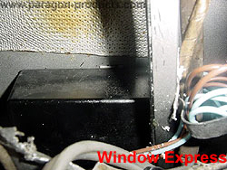
The circuit is housed in a small plastic box that fits in the door between the bottom of the front window track and the outer door skin (directly behind the front speaker hole on early cars), it is a tight fit but will not rattle or cause any problems. It is secured in place with double-sided foam tape (included, no drilling required).
-
-
The unit has five wires; two inputs, two outputs, and a ground.
-
The unit can be installed through the speaker hole in the early cars, but it is probably easier to remove the inner door panel.
-
Begin by removing the interior door panel. Make sure the window is closed. Remove the screws securing the door pocket, the armrest, speaker and interior door handle. There are also screws (capped) at the top front and top rear of the panel; these must be removed along with the locking button.
-
The panel is then only held on with plastic spring clips, carefully pry at these with a flat screwdriver. The panel must be slid upwards to disengage the armrest and the panel from the window track. It is also necessary to unplug the window switch and the mirror control switch. Carefully place the panel in a safe place.
-
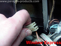
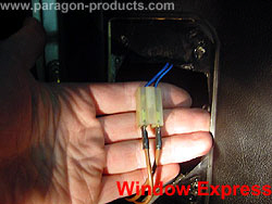
Reach through the speaker hole and find the plug on the bottom of the window motor. Disconnect this plug.
-
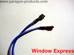
Plug the blue output wires from the module onto the spade connectors at the window motor, this is done by feel as you cannot see inside the door, do this first. The spade connectors provided in the kit fit directly.
-
Connect the two brown wires into the spade connectors in the plug that used to go to the motor. The spade connectors provided in the kit fit directly.
-
The ground wire (green / yellow) is fed up under the splash guard inside the door and through the alligator tube through into the door pillar, this may require using a draw wire of some sort to pull the wire through the holes. This is easier if you first pull the rubber boot away from the door and fish the wire in two stages: a) first through the door, and b) then through the rubber boot into the interior of the car. In other words, remove the boot, insert the chase wire at the opening into the door and under the splash guard, pull the ground wire, remove the fish wire from the ground wire, insert the fish wire through the boot into the interior, then pull the ground wire through the boot and into the interior (this is much easier than it sounds). The green wire can either be grounded at the steel underside of the dashboard or a small hole can be drilled in the nearby steelwork. Make sure it is a clean tight ground point or the unit will not function correctly.
-
On later LHD models, there is a factory installed grounding strip just above the hood release handle. This consists of a row of hex headed, brass bolts all of which are holding brown wires in place. It can be seen by laying on the seat and peering up under the dash. This is an excellent place to ground the switch as all one has to do is remove one of the bolts, slide the end of the green wire into place (it is designed to fit the bolt), and re-secure. Just be careful, if you chose not to disconnect the battery, to not touch any of the other wiring.
-
The car door cannot be used as a ground path as the doors on these cars are not electrically grounded except through the hinges.
-
The plastic casing is then fitted between the door outer skin and the bottom of the front window rail. The module is held in place with double-sided heavy-duty foam tape. This is industrial tape, which sticks really, really well. In fact, once applied, it is nearly impossible to reposition. The door skin must be cleaned with a solvent first for this to stick well. Check carefully and "test fit" before removing the backing paper from the foam tape. This sticks really well and cannot be repositioned easily.
-
Next connect up the window switch (either remove it from the panel or bring the panel close enough to connect).
-
Test the unit, if the button works in the wrong direction swap the two brown wires from the unit where they connect to the existing loom and test again.
-
Cable tie up all the wiring so it is well clear of the window and any other moving parts within the door.
-
Refit the door panel.
Notes:
-
What is really neat is if a second unit is installed on the passenger side, it will automatically work from both the passenger side AND THE DRIVER'S side switches. One unit will control one window.
-
If there is any problem with the unit, test your window by unplugging the unit and connecting the existing plug back to the motor, the switches fail on these cars quite often so this should be checked first. If the unit fails in any way send it back to us and we will repair or replace defective, not damaged, units for three years from the date of purchase as well as pick up return shipping costs. Owner is responsible for getting the unit to us in sound condition. Examples of "damaged" units include those with holes drilled in them, water logged units, and units with damaged or replaced wiring.
-
Kits can also be ordered for negative switched vehicles (both motor wires at 0v when motor is at rest), these kits are the same price. Separate instructions will be provided for these applications.
Tools: A few screwdrivers (and a small drill if you need to drill a hole for the ground connection) are all that is required for installation. No soldering or wire cutting needed.
Credits: Martin Taylor
| Related Articles |
> Front Shock Replacement
> A-arm bushing modification (65-68 911/912)
> Front Shock Replacement (65-89)
> Front Torsion Bars (65-89)
> Gate Shift Installation
> KLA Strut Brace Installation - 911
> KLA Strut Brace Installation - 964/993
> OXS light reset
> Front Torsion Bars
> What is the Largest Wheel and Tire Combination I can get under my stock 914 fenders?
> AC Delete
> Accusump Installation
> Adjustable Ride Height Kit - Paragon
> Alternator Replacement
> Brakes, front - 924S, 944, 944S
> Brey-Krause Strut Brace Installation - 944
> Camber Plate Installation (Paragon)
> Clock/Bulb Replacement, digital, Late 944 and 968
> Clutch Replacement - Part One
> Clutch Replacement - Part Two
> Clutch Slave Bleeder Valve Remote
> Control Arm Bushing Upgrade - Weltmeister
> Control Arm, Front - Info
> Coolant Flush
> DME Chip Installation
> KLA Boxster Top Fix
> Dash Replacement
> Engine Identification
> Engine Production
> Fuel Level Sender
> KLA Strut Brace Installation - 924S, 944, 968
> Koni Strut Conversion - 8641-1414S for late 944, 968
> Motor Mount Replacement
> Odometer Gear Replacement - late 944
> Oil Cooling, Auxiliary
> Oil Pressure Relief Valve
> Oil Pressure Sending Unit Replacement
> Rear Ride Height Adjustment
> Porsche Chronology
> Rear Spring Rates vs. Effective Rates
> Rear Wheel Bearing Diagnosis
> Rear Wheel Bearing Replacement - 924, early 944
> Rear Wheel Bearing Replacement - late 944, 968
> Ride Height Measurement
> Rod Bearing Replacement
> Shift Lever Rebuild
> Short Shift Kit
> Throttle Position Sensor
> Sway Bars - Info
> Torque Tube Rebuild
> Torsion Bar Replacement
> Transaxle Fluid - Info
> Transaxle Fluid Change
> Rear Sway Bar Installation
> Transaxle Replacement
> Heater Clip
> Window Regulator Replacement
> Seat Back Brace Installation Instructions
> Tarett Engineering Rear Sway Bar Installation Instructions
> Brey Krause Deep Sump Oil Pan Spacer Kit for
Porsche 996, Boxster, Boxster S
> RennShift 901 and 915 Installation Instructions (911 and 914 cars)
> KLA Strut Brace Installation - 968/944 S2/944 S
|
|
